
Taylor Race Engineering
Lightning Series Integrated Wheel Hub Core - 55mm
Lightning Series Integrated Wheel Hub Core - 55mm
Lightning Series Integrated Wheel Hub Core - 55mm
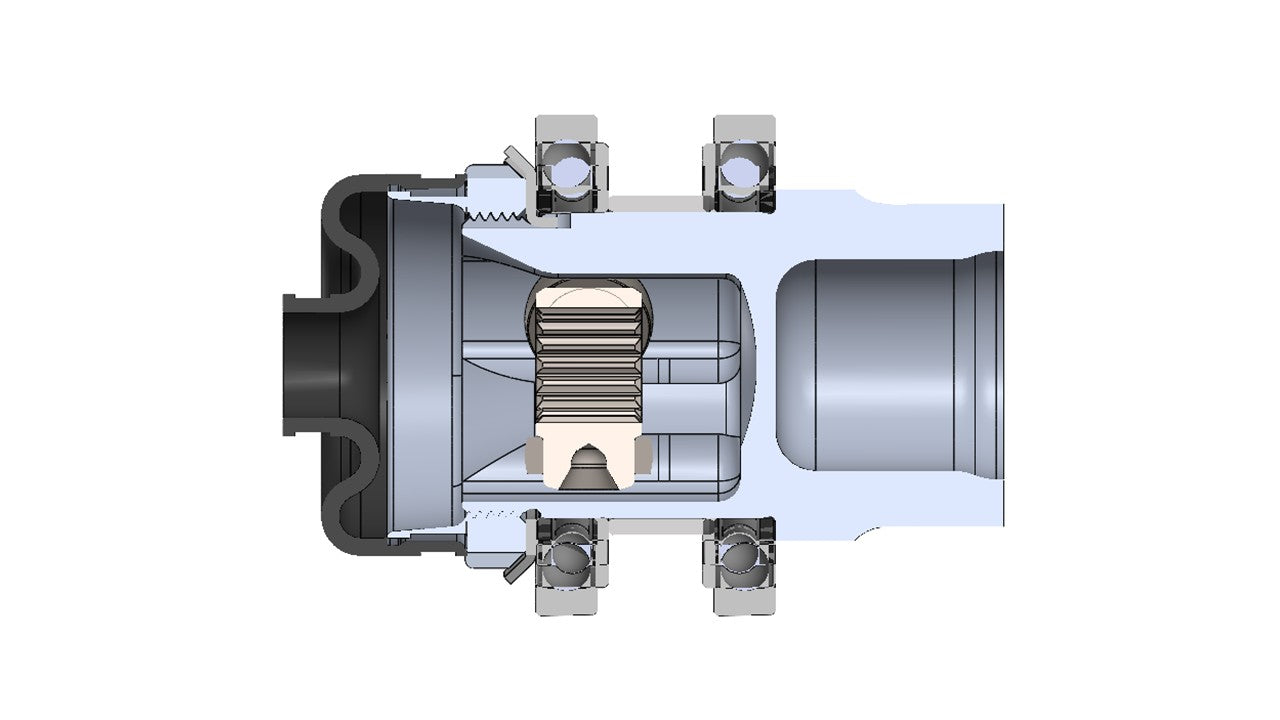
18T Lightning Series Tripod | 55mm Bearing Journal
Standard Core. Custom Interface. Custom Bearing Architecture.
The TRE Lightning Series 55mm Integrated Wheel Hub Core gives Formula SAE, Formula Student, Baja, and other lightweight vehicle designers a compact starting point for a fully integrated driven wheel end.
Unlike our 34mm and 44mm Modular Wheel Hub Systems, which are designed around specific sealed wheel-bearing units, the Lightning 55mm system intentionally leaves the bearing type and upright architecture open to the team.
TRE provides the difficult rotating core design: an integrated wheel hub and Lightning Series outboard tripod housing with a 55 mm bearing journal, controlled structural geometry, tab lock washer, and matching bearing clamping nut.
The team selects the bearing arrangement and designs the upright, wheel interface, brake rotor interface, and final corner packaging around its own vehicle.
The tripod housing, wheel hub, and bearing core become one component. Everything around it can be optimized for your car.
Integrated Lightning Series Tripod Housing
The 55mm hub is designed around TRE's compact 18-tooth Lightning Series FSAE tripod.
Instead of transferring torque through a separate outboard tulip, stub shaft, and wheel-hub spline, the tripod operates directly inside the rotating wheel hub. Drive torque passes from the tripod rollers directly into the hub body.
This integrated architecture can eliminate several components from a conventional driven wheel end:
- Separate outboard tripod housing or tulip
- Stub axle between the tripod housing and wheel hub
- Male/female wheel-hub spline
- Additional retention hardware associated with those interfaces
The result is a compact torque path and gives teams the opportunity to reduce component count, rotating mass, package length, and upright size.
The Lightning Series tripod was developed specifically around smaller FSAE drivetrain packages. Its compact joint envelope makes a 55 mm bearing journal practical while maintaining the plunge and articulation characteristics of a conventional tripod joint.
Choose Your Own Bearing Architecture
The Lightning 55mm hub uses a 55 mm bearing journal, but TRE does not require a particular wheel bearing.
That is deliberate.
Depending on the team's load requirements, upright design, manufacturing capability, stiffness targets, available space, and design philosophy, the hub can be integrated with several different bearing approaches.
Two simple deep-groove ball-bearing examples are:
6911-2RS / 61911-2RS1 Family
Nominal dimensions: 55 × 80 × 13 mm
16011 Family
Nominal dimensions: 55 × 90 × 11 mm
Bearing specifications, seals, internal clearance classes, tolerances, load ratings, and available suffixes vary between manufacturers. Teams should always design from the actual bearing manufacturer's data rather than assuming that matching boundary dimensions mean identical performance.
Other Bearing Types
The hub is not limited to standard deep-groove ball bearings.
Teams may choose to design around:
- Angular-contact ball bearings
- Tapered roller bearings
- Higher-precision bearing classes
- Different internal-clearance or preload specifications
- Other 55 mm-ID bearing arrangements that fit the available hub geometry
This allows the wheel bearing to become an intentional part of the suspension design rather than simply a catalog component selected after the upright is already designed.
43mm Bearing Spread
The standard Lightning 55mm hub geometry provides a 43 mm outside-to-outside bearing spacing.
Rather than placing two bearings directly beside one another, the separated arrangement gives the team a useful structural base for supporting wheel overturning moments and developing wheel-end stiffness.
Final corner stiffness still depends on the complete system:
- Bearing type and internal geometry
- Bearing spacing
- Upright stiffness
- Hub stiffness
- Bearing fits
- Wheel offset
- Bearing preload or operating clearance
- Material and temperature effects
The STEP model shows the standard TRE hub geometry and bearing locations so the team can design the upright around the actual rotating assembly.
We Recommend an Inner-Race Bearing Spacer
TRE strongly recommends using a precision spacer between the two bearing inner races.
The spacer allows the hub, bearing inner races, spacer, and supplied clamping nut to act as a controlled structural stack.
A properly engineered spacer can help:
- Establish repeatable bearing clamping
- Control the relative axial position of the bearing inner races
- Improve wheel-end stiffness
- Reduce sensitivity to assembly torque
- Prevent inappropriate axial loading of the bearings
- Produce a more repeatable service assembly
- Help achieve the intended bearing clearance or preload
The spacer should be treated as a precision engineering component. Its final length depends on the selected bearings, upright geometry, fits, tolerances, desired operating clearance or preload, materials, and temperatures.
Do not simply tighten the clamping nut until the bearings "feel tight."
Bearing Preload Matters
SKF Racing has published an excellent short technical note specifically addressing wheel-bearing preload in racing applications.
SKF identifies preload and clearance as important contributors to bearing life, camber stiffness, and friction. Their racing guidance notes that light preload is commonly used to improve load distribution, but that excessive preload causes bearing life to decrease as friction and operating temperature rise.
Their wheel-end example is particularly relevant to this system because it shows a pair of separated bearings with a hub, upright, inner spacer, and retaining nut - essentially the same design problem teams are solving with the Lightning 55mm core. SKF identifies several factors that must be considered together when determining the actual preload:
- Bearing, hub, upright, and spacer stiffness
- Hub, upright, and spacer materials
- Bearing fits
- Nut torque
- Mounting and operating temperature
SKF also emphasizes that preload cannot simply be directly measured after assembly in the same way that endplay can.
Recommended Reading
SKF Racing - Wheel Bearing Preload in Racing Applications
[DOWNLOAD / VIEW SKF TECHNOTE]
For teams doing a more detailed bearing analysis, SKF's current bearing-preload technical publication also discusses using intermediate rings, shims, and spacers between bearing inner rings to establish the desired preload or operating clearance.
Designed Around Your Wheel and Brake Package
As with the TRE 34mm and 44mm Modular Wheel Hub Systems, the wheel side of the Lightning hub is intentionally provided as a configurable design region rather than forcing the team into a predetermined wheel bolt pattern, brake rotor, or wheel offset.
Within the approved design envelope outboard of the bearing system, teams can define features including:
- Wheel bolt or stud pattern
- Center pilot diameter
- Wheel mounting-face location
- Brake rotor bolt pattern
- Rotor pilot
- Rotor offset
- Flange outside diameter and profile
- Appropriate lightening geometry
This allows the Lightning hub to work with 10-inch, 13-inch, and other custom Formula SAE wheel and brake packages.
You can manufacture the custom hub yourself, work with a local machine shop, or have TRE manufacture the completed part.
From an educational standpoint, we encourage teams with the resources and capability to experience the design and manufacturing process themselves. There is real engineering value in understanding machining access, workholding, distortion, tolerances, inspection, cost, and risk.
TRE can provide engineering consultation whether we manufacture the final hub or your team does.
Why Use an Integrated Hub System?
Wheel hubs are deceptively difficult components. They combine wheel loads, braking loads, drive torque, bearing fits, bearing stiffness, retention, fatigue, manufacturing tolerances, and drivetrain packaging into a very small assembly.
An integrated tripod wheel hub adds another challenge: the outboard CV joint and wheel bearing system occupy the same space and carry loads through the same structure.
The Lightning Series 55mm Wheel Hub Core gives teams a developed starting point for that architecture while preserving the engineering freedom to optimize the rest of the corner.
The system allows teams to optimize:
- Bearing type
- Bearing diameter
- Bearing preload
- Bearing spacing
- Upright mass and stiffness
- Wheel offset
- Brake package
- Wheel attachment
- Drivetrain packaging
without having to redesign the Lightning Series tripod housing itself.
STEP Assembly Download
The downloadable STEP assembly shows:
- Lightning Series integrated hub geometry
- Tripod and roller operating envelope
- 55 mm bearing journal
- 43 mm bearing spacing
- Clamping nut
- Example bearing arrangement
- Example upright packaging
- Tripod boot interface
[DOWNLOAD STEP - LIGHTNING SERIES 55MM INTEGRATED WHEEL HUB]
The STEP assembly is provided as a packaging and integration model.
Teams are encouraged to modify the wheel, brake, bearing, spacer, and upright design around the TRE core, but should contact TRE before modifying the tripod tracks, bearing journal, clamp interface, or other controlled core geometry.
Need Help Designing the Corner?
Contact TRE to schedule an engineering consultation.
Together, we can review:
- Wheel and tire
- Brake rotor and caliper
- Upright concept
- Bearing selection
- Bearing spacing
- Preload or clearance strategy
- Inner-race spacer design
- Wheel and rotor offsets
- Suspension loads
- Vehicle mass
- Halfshaft length
- Tripod plunge
- Maximum tripod articulation
TRE can help determine whether the Lightning Series integrated architecture makes sense for your car and help identify areas where the wheel-end design can be made lighter, stiffer, simpler, or easier to manufacture.
Couldn't load pickup availability